
Abstract
The future exploration of space by humans heavily relies on the development of highly efficient launch options that can utilize in-situ energy. Most conventional propulsion systems are bottlenecked by chemical reactions. This creates a severe limitation in deep space or alien environments where chemical fuels are scarce. Furthermore, while nuclear fuels offer massive energy density, they cannot easily be used directly in traditional exhaust-based propulsion systems.
Electromagnetic accelerators provide a groundbreaking alternative. By utilizing pure electromagnetic forces for propulsion, they provide a massive advantage in resource-limited environments. In these scenarios, electricity can be generated steadily using nuclear or solar energy, which is then used directly to power propulsion systems like electromagnetic mass drivers.
Hardware Architecture
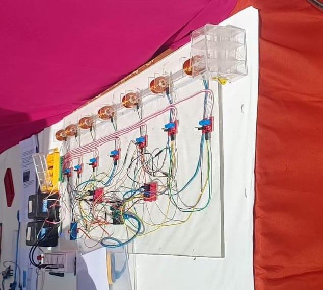
The successful acceleration of a physical payload requires precise orchestration between high-voltage power delivery and microsecond-accurate digital switching. The hardware stack consists of:
- Copper Coils: Carefully arranged in a linear, multi-stage sequence. These coils generate the intense, localized magnetic fields responsible for accelerating the payload forward.
- Hall Effect Sensors: Positioned strategically at each stage to detect the precise physical presence and magnetic signature of the payload as it travels through the accelerator.
- Arduino Microcontrollers: The brain of the operation. These microcontrollers are programmed to read the real-time telemetry from the Hall sensors and fire "High" or "Low" signals to the switching array.
- IRF520 MOSFET Array: Solid-state switches responsible for instantly turning the high-voltage coils on and off based on the Arduino's logic. The IRF520 module was specifically selected because it boasts a breakthrough voltage of 100V, ensuring stable operation without hardware failure under heavy load.
- Dual Power Sources: A standard 5V DC power source is used to safely run the delicate digital control logic (Arduinos and sensors), completely isolated from a high-voltage 50V-70V DC power line used exclusively to energize the propulsion coils. This high voltage was achieved by bridging two separate 30-35V DC power sources in series.
Working Mechanism
The core innovation of this project lies in the construction of a multi-stage coil accelerator, where every individual coil is dynamically governed by the Arduino and MOSFET controller.
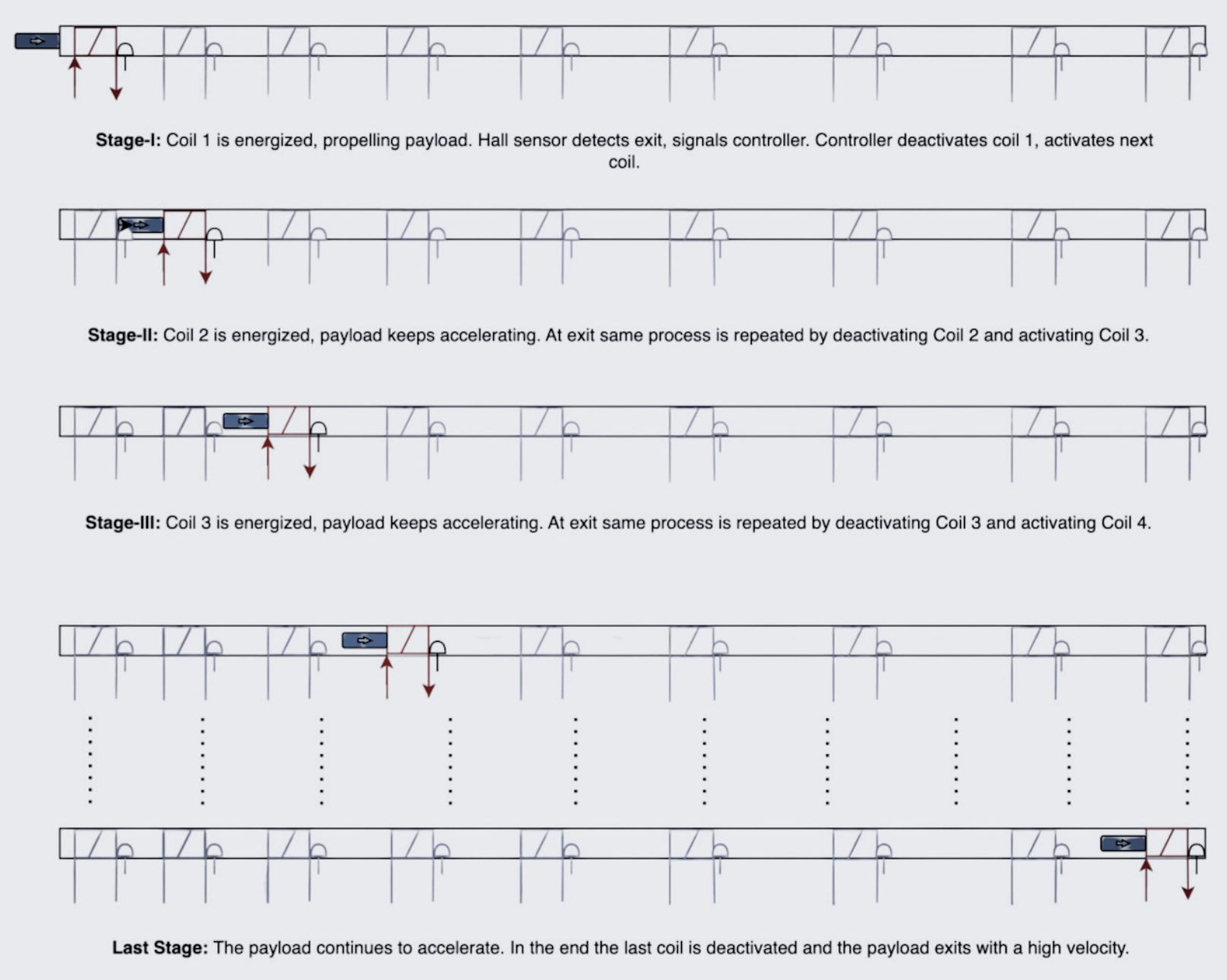
Rather than firing all coils at once, the accelerator energizes the payload strictly sequentially. As the payload is pulled toward the first coil, its arrival is instantly detected by the local Hall effect sensor. This triggers an immediate digital interrupt: the microcontroller deactivates the current coil to prevent the payload from getting stuck in magnetic equilibrium, while simultaneously activating the next coil down the line. This rapid, cascading sequence pulls the payload faster and faster, building significant high-velocity momentum.
Control Logic (Arduino)
The acceleration sequence is orchestrated by a central Arduino. The logic utilizes hardware interrupts (simulated via rapid polling) to track the payload across six dedicated Hall effect sensors. To prevent coil burnout under high voltage, a strict stopTime safety threshold automatically kills power to all coils after 2000 milliseconds.
// Pin Definitions
const int COIL1_PIN = 2;
const int COIL2_PIN = 4;
const int COIL3_PIN = 6;
const int COIL4_PIN = 8;
const int COIL5_PIN = 10;
const int COIL6_PIN = 11;

const int SENSOR1_PIN = 1;
const int SENSOR2_PIN = 3;
const int SENSOR3_PIN = 5;
const int SENSOR4_PIN = 7;
const int SENSOR5_PIN = 9;
const int SENSOR6_PIN = 11;

// Variables for Sensor Readings
int sensor1State;
int sensor2State;
int sensor3State;
int sensor4State;
int sensor5State;
int sensor6State;

// Time Variables
unsigned long startTime;
unsigned long elapsedTime;
const unsigned long stopTime = 2000;

void setup() {
  // Set Coil Pins as Outputs
  pinMode(COIL1_PIN, OUTPUT);
  pinMode(COIL2_PIN, OUTPUT);
  pinMode(COIL3_PIN, OUTPUT);
  pinMode(COIL4_PIN, OUTPUT);
  pinMode(COIL5_PIN, OUTPUT);
  pinMode(COIL6_PIN, OUTPUT);

  // Initialize Coil States (Fire first coil to pull payload)
  digitalWrite(COIL1_PIN, HIGH);
  digitalWrite(COIL2_PIN, LOW);
  digitalWrite(COIL3_PIN, LOW);
  digitalWrite(COIL4_PIN, LOW);
  digitalWrite(COIL5_PIN, LOW);
  digitalWrite(COIL6_PIN, LOW);

  // Record Start Time
  startTime = millis();
}

void loop() {
  // Update Elapsed Time
  unsigned long currentTime = millis();
  elapsedTime = currentTime - startTime;

  // Safety Check: Turn off coils if program runs past 2 seconds
  if (elapsedTime > stopTime) {
    digitalWrite(COIL1_PIN, LOW);
    digitalWrite(COIL2_PIN, LOW);
    digitalWrite(COIL3_PIN, LOW);
    digitalWrite(COIL4_PIN, LOW);
    digitalWrite(COIL5_PIN, LOW);
    digitalWrite(COIL6_PIN, LOW);
  } else {
    // Read Sensor States
    sensor1State = digitalRead(SENSOR1_PIN);
    sensor2State = digitalRead(SENSOR2_PIN);
    sensor3State = digitalRead(SENSOR3_PIN);
    sensor4State = digitalRead(SENSOR4_PIN);
    sensor5State = digitalRead(SENSOR5_PIN);
    sensor6State = digitalRead(SENSOR6_PIN);

    // Cascade Coils based on Sensor Triggers
    if (sensor1State == LOW) {
      digitalWrite(COIL1_PIN, LOW);
      digitalWrite(COIL2_PIN, HIGH);
    }
    if (sensor2State == LOW) {
      digitalWrite(COIL2_PIN, LOW);
      digitalWrite(COIL3_PIN, HIGH);
    }
    if (sensor3State == LOW) {
      digitalWrite(COIL3_PIN, LOW);
      digitalWrite(COIL4_PIN, HIGH);
    }
    if (sensor4State == LOW) {
      digitalWrite(COIL4_PIN, LOW);
      digitalWrite(COIL5_PIN, HIGH);
    }
    if (sensor5State == LOW) {
      digitalWrite(COIL5_PIN, LOW);
      digitalWrite(COIL6_PIN, HIGH);
    }
    if (sensor6State == LOW) {
      digitalWrite(COIL6_PIN, LOW);
    }
  }
}Future Applications
This prototype successfully demonstrates the foundational physics and control logic required for electromagnetic propulsion, proving its adaptability for future transport solutions.
Electromagnetic catapults could be engineered for low-gravity environments (like the Moon or asteroids) to launch miniature satellites or payload containers without using a drop of chemical fuel, unlocking the economic viability of asteroid mining ventures.
The underlying technology holds immense promise for terrestrial industrial applications. High-speed, frictionless material transport systems could deliver massive efficiency gains and cost savings in manufacturing logistics.
Scaling up this technology paves the way for electromagnetic railguns. These systems offer hyper-velocity projectile capabilities, providing advanced solutions for long-range precision strikes and missile defense.
By showcasing the construction and operation of a multi-stage coil accelerator controlled by Arduino boards and MOSFET switches, we highlight the adaptability and sustainability of electromagnetic propulsion for future space exploration.